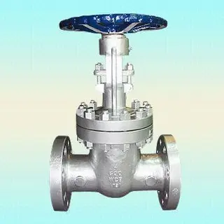
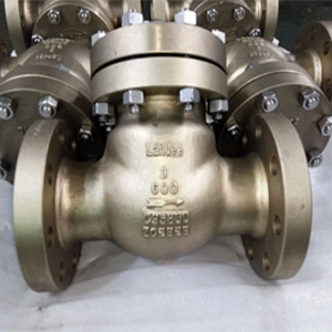
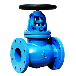
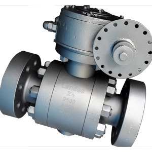
The manual welded ball valve is a type of valve that achieves fluid on and off control through manual operation. Its core structure consists of a ball and a valve seat that are matched and connected to the pipeline through welding. The following is a detailed explanation of its key characteristics and working principle.
The Q61F welded ball valve is widely used in various fields. Its quality and high-performance stability cannot be achieved by ordinary cast steel ball valves, and its service life is much longer than that of cast steel ball valves. Welded ball valves are widely used in various pipeline equipment such as urban gas, urban heating, petrochemicals, shipbuilding, steel, pressure regulating stations, power plants, etc. Welded ball valves can operate reliably for a long time, require maintenance, are easy to install, and are more convenient to install.
Advantages of Q61F Manual Welded Ball Valves
1. International Certificates and Standards
2. Specialized design for pipeline applications of gasoline (liquefied natural gas/liquefied petroleum gas)
3. Can have the same lifespan as the pipeline system
4. Free maintenance, no need for adjustment or lubrication, low operating costs
5. Bidirectional valves can be used with special coatings for corrosion prevention.
Main Features of Q61F Manual Welded Ball Valves
1. Connect one end to the valve body and the other end to the pipeline (note: the size standards for connecting ends are ASTM, EN, KS/JIS, etc.)
2. Mirror polishing requires inspection of the entire stainless steel sphere.
3. Bubble tight sealing and carbon reinforced PTFE (Teflon) valve seat
4. Pre-loaded seat cushion spring ensures tight low-temperature leakage and reduces valve operation torsion force.
5. Oppose bursting valve stems according to international standards
6. Two O-rings ensure valve stem sealing and replaceable
7. Automatic lubrication capability of valve stem dry bearings and metal with PTEF coating, without the need for additional lubricants
8. The valve stem and port connecting pipeline can be extended according to customer design requirements.
Materials of Q61F Manual Welded Ball Valves
1. Valve body: Carbon steel ST37, A106-B, STPG 370, A105, ASTM A516-60, A216-WCB or equivalent. Stainless steel 304 or 316 (choose according to requirements)
2. Sphere: Stainless steel 304 or 316 grade
3. Valve seat: PTFE, reinforced PTFE, Nylon, Peek, etc
The Purpose of Selection and Analysis of Q61F Manual Welded Ball Valves
Urban gas: gas output pipelines, main and branch supply pipelines, etc.
Central heating: large heating equipment output pipelines, main lines, and branch lines
Heat exchanger: opening and closing of pipelines and various circuits
Steel plant: various fluid pipelines, exhaust gas selection pipelines, gas and heat supply pipelines, fuel supply pipelines
Various industrial equipment: various heat treatment pipelines, various industrial gas and heat pipelines
Characteristics of Selection and Analysis of Q61F Manual Welded Ball Valves
There will be no external leakage or other phenomena. As the valve seat is composed of a carbonized PTFE sealing ring and a coffee spring, it has strong adaptability to changes in pressure and temperature, and there will be no leakage within the marked pressure and temperature range. The machining process of the sphere is well tracked and detected by a computer detector, which ensures high machining accuracy of the sphere. Due to the fact that the valve body material is the same as the pipeline material, there will be uneven stress, and it will not deform due to earthquakes or vehicles passing through the ground. The pipeline is resistant to aging. The sealing ring body is made of PTFE material with a carbon content of 20%, ensuring no leakage (0%).
Valve Body Technical Treatment of Q61F Manual Welded Ball Valves
Everyone must have seen the valve body of a fully welded ball valve, and they know that the welding joints are generally designed as narrow gap thick wall submerged arc welding, and the fully welded valve body is mostly a super thick cylindrical welding joint. Everyone must want to know why, right?
1. Heat treatment technology
The thick walled multi-layer welding process is a process in which metal materials are repeatedly heated and cooled, resulting in uneven and inferior welding joint structure, high residual stress, and even welding defects. Welding is the final process after the assembly of the product, and there are non-metallic sealing materials such as rubber and polytetrafluoroethylene plastic in the valve chamber, which cannot be subjected to post weld heat treatment.
2. Joint processing
In the design of valve body welding joints, in order to align and position, there is a circular assembly gap at the root of the weld. This gap will generate stress concentration several times the normal working stress under internal pressure and external load, which also makes it difficult for engineers to handle.
The stress concentration and residual stress in the root gap of the welded joint of the valve body have become weak links in the structure of the valve body, which has attracted attention from the valve industry at home and abroad. However, there have been no relevant reports to solve this problem, which has become a hidden danger to the integrity of the product structure boundary.
Selection Analysis of Q61F Manual Welded Ball Valves
1. Structural Composition
Sphere: The core component of a valve, usually a solid metal sphere, with a surface that has been precision ground to ensure a tight fit with the valve seat and achieve sealing.
Valve seat: Surrounding the sphere, made of wear-resistant and corrosion-resistant materials (such as PTFE, metal hard seal), providing bidirectional sealing function.
Valve stem: It connects the ball to the operating handle, transmits rotational torque, and drives the ball to rotate.
Welding end: The valve is welded at both ends (such as butt welding, socket welding) and directly fixed to the pipeline without flange connection, reducing leakage points.
2. Working Principle
Open state: Manually rotate the handle 90 degrees, align the spherical channel with the pipeline axis, and allow fluid to pass freely.
Closed state: Rotate the handle 90 degrees in reverse, with the spherical channel perpendicular to the pipeline axis, blocking fluid flow.
Sealing mechanism: When closed, the ball tightly presses against the valve seat under the pressure of the medium, forming a metal or soft seal to prevent leakage.
3. Core Features
High sealing performance: Welding connection eliminates the risk of flange gasket leakage, and it is suitable for high pressure, high temperature or corrosive media.
Compact structure: The flange free design reduces space occupation and is easy to install in narrow environments.
Strong pressure resistance: Welded structures can withstand higher pressures (usually up to Class 600 and above). It's suitable for high-pressure conditions such as petroleum and chemical industries.
Wide temperature resistance range: The metal ball and valve seat can adapt to temperatures ranging from -196 ℃ to 600 ℃.
Long lifespan: Precision machined spheres and valve seats reduce wear and have a long maintenance cycle.
4. Applications
High pressure pipeline system: such as natural gas transportation and high-pressure steam pipelines in refineries.
Corrosive media: acid-base solutions in the chemical industry, seawater desalination systems.
Low temperature conditions: liquefied natural gas (LNG) storage and transportation, low-temperature laboratory.
Underground pipeline: Welding connection to resist external impact, and it's suitable for underground or submarine pipelines.
5. Operation and Maintenance
Operation method: Manually rotate the sphere through a handle, worm gear, or electric actuator.
Maintenance points:
Regularly inspect the welding end for cracks or corrosion.
Lubricate the valve stem to reduce operating torque.
Replace worn valve seats (hard sealed valves require professional maintenance).
Summary
Manual welded ball valves are integrated with pipelines through welding connections, making them an ideal choice for high-pressure, corrosive, or temperature conditions due to their high sealing, pressure resistance, and compact structure. Its design simplifies the system structure, but it is necessary to ensure welding quality during installation and regularly check the integrity of the welding ends.
Q61F three piece butt welded ball valve is suitable for various pipelines with PN 1.0 to 6.4MPa, working temperature -29 to 180 ℃ (sealing ring is reinforced polytetrafluoroethylene) or -29 to 300 ℃ (sealing ring is para polystyrene), used for cutting off or connecting media in pipelines. By selecting different materials, it can be applied to various media such as water, steam, oil, nitric acid, acetic acid, etc.
Product Features of Q61F Manual Welded Ball Valves
1. It consists of three parts for easy maintenance and replacement in the later stage.
2. Excellent silica sol process, with a reasonable structure and beautiful appearance.
The valve seat adopts an elastic sealing structure, which is easy to open and close, lightweight, and has good sealing performance.
The valve stem adopts a reverse sealed bottom mounted structure, which prevents the valve stem from flying out due to internal pressure, ensuring safety.
1. Prepare Tools and Materials
Welding ball valves, welding equipment, welding materials, and welding auxiliary tools (such as welding fixtures).
2.Clean the Welding Surface
Use cleaning tools such as wire brushes to remove dirt and oxides from welded ball valves and pipe connections, ensuring a clean connection surface.
3. Adjust Welding Equipment
Adjust the parameters of the welding equipment according to the welding method used to ensure welding quality.
4. Welded Ball Valves
Insert the welded ball valve into the connection port and use a welding fixture to fix the position of the ball valve and pipeline connection port, ensuring alignment between the ball valve and the pipeline.
5. Perform Welding
Use appropriate welding methods (such as TIG welding, arc welding, etc.) to weld according to the requirements for welding ball valve materials.
6. Check Welding Quality
After welding is completed, check the weld seam and welding quality to ensure that the welding is firm and free of obvious defects.
7. Cleaning and Painting
Clean the welding area, remove welding residue and dirt, and apply paint protection as needed.
8. Installation and Testing
Install the welded ball valve into the system and conduct testing to ensure its normal operation and reliable sealing.
Please note that this is only a general welding ball valve installation method, and the specific operating steps and requirements may vary depending on different situations. Before installation, please read the user manual of the ball valve carefully and follow the manufacturer's instructions for operation. At the same time, welding equipment and operators should receive corresponding training and certification before installation to ensure safety and quality.