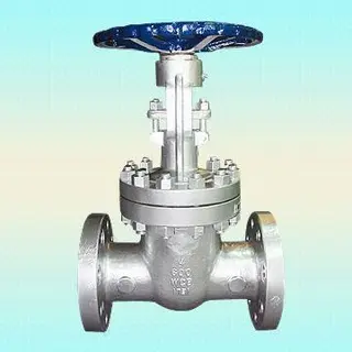
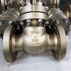
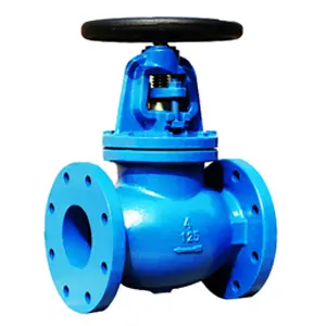
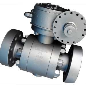
Here is the introduction to the principle and function of pneumatic cut-off valves.
The pneumatic cut-off valve is a key equipment used in automation control systems to quickly cut off or connect fluids. Its core function is to respond to control signals to achieve emergency cut-off or process switching, ensuring system safety. The main characteristics and classifications are as follows.
1. Structural composition
Execution mechanism: Adopting pneumatic diaphragm or piston structure, it receives compressed air signal (usually 0.4 to 0.6MPa) to drive the valve core action.
Valve body types: it includes single seat valves, double seat valves, sleeve valves, ball valves, etc., and is suitable for different pressure differentials and sealing requirements.
Sealing design: it is divided into hard sealing (high temperature resistance) and soft sealing (tight cut-off), some valves have fire and static electricity prevention functions, and prevent flammable media from igniting through conductive springs.
2. Core features
Action speed: Cut off response time ≤ 0.1 seconds (fast type) or ≤ 1 second (conventional type). It can instantly block the medium in emergency situations.
Reliability: The spring reset design ensures automatic closing (gas closed) or opening (gas open) when power or gas is cut off.
Applicable media: gases, liquids (without particle impurities), such as natural gas, liquid ammonia, steam, etc.
3. Classification and applications
Type: characteristics, and typical Applications
Ordinary cut-off valves: simple structure, sensitive response, conventional cut-off for petroleum and chemical pipelines
Quick emergency shut-off valves: response time<0.1 seconds, including fusible alloy fuse (automatically blown at 70 degrees), gas leakage, fire emergency
Pneumatic cut-off ball valves: full bore or reduced diameter design, low flow resistance for viscous media (such as petroleum) and gas pipelines
Anti-dust special valves: wear-resistant structure, metallurgical flue gas, gas dust containing working conditions
4. Selection and installation points
Air source requirements: Clean compressed air needs to be filtered to prevent blockage of the actuator.
Working condition adaptation: Choose hard seal for high temperature environment (≤ 550 degrees). Stainless steel valve body for corrosive media.
Safety linkage: cooperate with solenoid valves and leak alarms to achieve automatic control.
5. Industry applications
Energy security: Explosion proof cut-off of gas pipelines (such as corresponding to domestic ZSQP type).
Chemical protection: Emergency shutdown of liquid ammonia storage and transportation system.
Environmental governance: Air volume regulation and emergency isolation of flue gas treatment system.
Note: During installation, it is necessary to ensure the accuracy of the transmission shaft and the reliability of the spring components to maintain long-term stable operation.
6. Use and maintenance of pneumatic cut-off valves
The following is a comprehensive explanation of the use and maintenance points of pneumatic cut-off valves. It is organized based on equipment characteristics and industry standards.
(1). Operation and usage standards
Use and maintenance of pneumatic cut-off valves
Gas source management
Use filtered clean compressed air (pressure 0.4-0.7MPa) and regularly clean the filter to prevent impurities from clogging the actuator.
The air source treatment requires three components (filter, pressure reducing valve, oil mist device), and the oil mist volume should be adjusted to 1 to 2 drops per minute.
Opening and closing operation
Air Open (FO): The ventilation is turned on, and the spring resets and closes when the air is cut off (safety mode).
Gas closed (FC): The ventilation is closed, and the spring returns and opens when the gas is cut off.
Manual emergency: Rotate the handwheel when the gas is cut off, and the handwheel should be in the closed state during normal pneumatic control.
Linkage control
Interlock with solenoid valve and leakage alarm to achieve automatic cut-off (response time ≤ 0.1 seconds).
Fireproof design: The fusible plug automatically melts and releases pressure at 70 ± 5 degrees, and the valve closes urgently.
(2). Key points of maintenance and upkeep
Regular maintenance project
Daily inspection: stability of gas source pressure, leakage check, pressure fluctuation are less than 0.05MPa, and no air leakage in the trachea.
Monthly maintenance: Cylinder sealing, piston rod lubrication, application of silicone grease, inspection of piston rod for scratches
Quarterly maintenance: Clean the filter element and check the reset spring. If the pollution level of the filter element exceeds 80%, it needs to be replaced. The spring should not be corroded or deformed.
Annual maintenance: Wear detection of valve seat sealing surface, functional testing of fire prevention mechanism, hard seal wear are less than 0.5mm, and soft seal is without aging cracks.
Key maintenance measures
Sealing maintenance
Soft seal (PTFE) should be regularly inspected for aging, while hard seal (alloy surface) should be returned to the factory for repair if the wear exceeds the limit.
When the stuffing box leaks, tighten the gland nut or replace the graphite packing.
Action performance calibration
The full travel time should be controlled within three to eight seconds. If it is too fast, it may cause a water hammer effect, and if it is too slow, it will affect the cutting speed.
Adjust the limit switch with a 5-degree mechanical margin to prevent damage to the gearbox caused by excessive torque.
Emergency function testing
Simulate gas or power outages every six months to verify the spring reset speed and sealing effect (leakage after closure ≤ ISO 5208).
(3). Troubleshooting guide
Fault phenomenon: possible causes and solutions
Poor valve closure: impurities in the valve core, damage to the sealing surface, cleaning of the valve chamber, grinding or replacement of the valve seat
Action delay: Insufficient air source pressure or piston jamming, check the pressure reducing valve, clean cylinder impurities and lubricate
Reset failure: Spring fracture or transmission shaft deformation, replacement of spring, correction of valve stem straightness
Abnormal signal feedback: Position sensor offset or electromagnetic interference, recalibration of feedback rod gap, installation of shielding cover
(4). Notes for special working conditions
Low temperature environment (<-20 degrees): Replace the low-temperature sealing grease and add electric heat tracing to the gas path to maintain a temperature of 5 degrees or above.
Explosion proof area: The actuator must meet the Exd Ⅱ CT6 explosion-proof rating, and the cable interface must be tightened with double nuts.
Corrosive medium: The valve body is made of 316L stainless steel and regularly flushed to prevent crystallization.
Note: Maintenance operations must follow the equipment manual, and when welding installation is involved, the valve should be opened to protect the sealing surface.