Pipelines cannot be replaced just like DN. Gate valves and globe valves are determined by their structure. The gate valve has heavy flow resistance, and it can be fully opened and fully closed. The key to a globe valve is stable shut-off, but the flow direction must not be reversed. Choosing the wrong structure may result in high-pressure drop, poor sealing, and erosion of the sealing surface in the later stage.
In pipeline systems, gate valves and globe valves are often compared together. Because they can all be used in cutting conditions, flange connections are common at both ends, and materials such as stainless steel and carbon steel can also be used. Many people only consider the diameter, pressure, and material when selecting valves, thinking that if DN, PN, and flange are the same, they can be replaced at will.
In fact, the structure of gate valves and globe valves is completely different. Gate valves are opened and closed by lifting the gate up and down, while globe valves are cut off by pressing the valve disc against the valve seat. Different structures result in different flow resistance, installation direction, sealing characteristics, and applicable working conditions.
Firstly, what are the characteristics of gate valves?
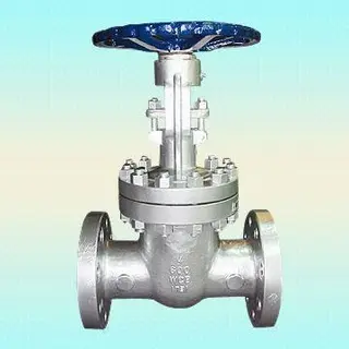
The opening and closing component of a gate valve is the gate plate. When opened, the gate rises upwards and the medium passes through. When closed, the gate is pressed down to the valve seat position, and the pipeline is cut off.
The biggest feature of a gate valve is that the flow path is relatively smooth when fully opened, and the gate valve basically exits the flow path, resulting in relatively low resistance for the medium to pass through. Thus, it is commonly used in main pipelines, water supply and drainage, circulating water, steam, oil products, and general industrial pipelines.
Gate valves are suitable for long-term full opening or full closing, and are not suitable for frequent and rapid opening and closing, nor for long-term semi-opening flow regulation.
Secondly, what are the characteristics of globe valves?
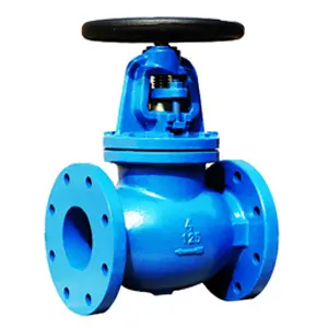
The opening and closing component of the globe valve is the valve disc. The valve stem drives the valve disc to move up and down. When the valve disc leaves the valve seat, the medium passes through. When the valve disc presses against the valve seat, the pipeline is cut off.
The closing action of the shut-off valve is relatively direct, and the sealing force is clear, so it is more common in positions such as steam, hot water, thermal oil, industrial gas, and equipment inlet and outlet.
But the internal flow channel of the globe valve has obvious turns, and the pressure drop when the medium passes through is usually greater than that of the gate valve. When installing, also check the flow direction arrow of the valve body, and do not install it upside down casually.
Simply put, globe valves are more suitable for pipelines with clear medium flow direction, reliable shut-off, and acceptable pressure drop.
Thirdly, there is a significant difference in flow resistance.
After the gate valve is fully opened, the medium flows smoothly and the flow resistance is relatively small. Therefore, in some main pipelines, large-diameter pipelines, and locations that operate fully open for a long time, gate valves are more common.
The internal flow channel of the globe valve is not a straight through structure, and the medium needs to be diverted, resulting in relatively higher flow resistance and pressure drop. If the system is very sensitive to pressure drop, globe valves cannot replace gate valves casually. Therefore, as a shut-off valve, if the pipeline is running fully open for a long time and you want to reduce flow resistance, a gate valve is more suitable. If more emphasis is placed on reliability and the system allows for a certain pressure drop, globe valves are more suitable.
Fourthly, the installation flow direction is different.
Gate valves generally have less obvious flow requirements than globe valves, and many ordinary gate valves can be used for bidirectional flow. The shut-off valve is different. Globe valves usually have a clear flow direction and arrow markings on the valve body. During installation, the direction of the arrow should be consistent with the flow direction of the medium. If the shut-off valve is installed in reverse, problems such as difficulty in opening and closing, increased pressure drop, abnormal force on the valve disc, and unstable sealing may occur. In severe cases, the valve may not close tightly or its service life may decrease. Therefore, when choosing a globe valve, you can't just look at whether the flange can be connected, but also consider the flow direction of the medium on site.
Fifth, can it be used to adjust traffic?
Gate valves are not suitable for long-term semi-open flow regulation. When the gate is stopped in the middle position, the medium will wash the edge of the gate and the sealing surface of the valve seat at high speed, which can easily lead to internal leakage over time.
Although globe valves are easier to affect flow through opening than gate valves, ordinary globe valves are not equivalent to professional regulating valves. Long term low opening operation will also cause erosion of the valve disc and seat, especially under steam, high temperature water, and high pressure differential conditions.
If the system requires long-term stable flow regulation, a regulating valve should be selected instead of letting ordinary gate valves or ordinary globe valves undertake the regulation task for a long time.
Sixth, the larger the caliber, the more obvious the difference.
In small-diameter pipelines, the volume difference between gate valves and globe valves may not be particularly significant. But after the caliber increases, the difference becomes very obvious.
Large diameter gate valves are suitable for cutting off main pipelines. Although they are relatively high, they have lower flow resistance when fully opened.
Large caliber globe valves may have significant volume and pressure drop, and may require greater operating force, which may not be suitable for all main pipelines.
Thus, the selection of large-diameter pipelines cannot be based solely on the ability to cut off, but also depends on the system flow rate, pressure drop requirements, and operating frequency.
Seventh, how to judge when selecting?
You can judge according to this idea.
If it is the main pipeline and it is fully open or closed for a long time, if the flow resistance is low, gate valves can be prioritized.
If it is steam, hot water, thermal oil, or equipment inlet and outlet that need to be reliably shut off, a shut-off valve can be considered.
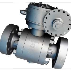
If frequent and fast switching is required on site, neither may be suitable, and ball valves can be considered.
If continuous flow regulation is required on site, regulating valves should be considered.
If the installation space is limited above, it should be noted that the valve stem will rise after the rising stem gate valve is opened. If it is a globe valve, it is important to confirm the flow direction and pressure drop.
Summary
Both gate valves and globe valves can be used for pipeline cutting, but they cannot be easily interchanged.
Gate valves are suitable for fully open and fully closed, low flow resistance, and main pipeline cut-off. Globe valves are suitable for working conditions with clear flow direction, reliable closure, and acceptable pressure drop.
Simply put, for gate valves, check whether the flow resistance is low or not, and for globe valves, check whether the shut-off is stable or not. When selecting, do not only consider the DN diameter, PN pressure, and flange standard, but also the medium, flow direction, pressure drop, opening and closing frequency, and installation space. Only by selecting the right structure can the valve work stably. Choosing the wrong structure can lead to heavy switching, high pressure drop, erosion of the sealing surface, and poor sealing in the later stages.
Previous: Selection of Common Valves